
The hydraulic drive of the brakes and clutch of cars contains a unit that facilitates the control of these systems - a vacuum amplifier. Read all about vacuum brake and clutch boosters, their types and designs, as well as the selection, repair and replacement of these units in the article presented on the website.
What is a vacuum amplifier?
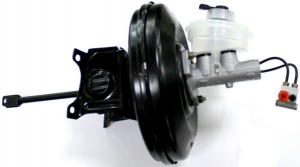
Vacuum booster (VU) - a component of the brake system and clutch with a hydraulic drive of wheeled vehicles; A pneumomechanical device that provides an increase in force on the brake or clutch pedal due to the difference in air pressure in insulated cavities.
The hydraulically operated braking system used on most cars and many trucks has a serious drawback - the driver has to exert significant force on the pedal to perform braking. This leads to increased driver fatigue and creates dangerous situations when driving. The same problem is observed in the hydraulically operated clutch that many trucks are equipped with. In both cases, the problem is solved by using one pneumomechanical unit - a vacuum brake and clutch booster.
The VU acts as an intermediate link between the brake / clutch pedal and the brake master cylinder (GTZ) / clutch master cylinder (GVC), it provides an increase in the force from the pedal several times, which makes it easier to control the vehicle. This unit is important for the safe operation of the car, and although its breakdown as a whole does not interfere with the operation of the brake / clutch drive, it must be repaired and replaced. But before buying a new vacuum amplifier or repairing an old one, you need to understand the existing types of these mechanisms, their design and principle of operation.
Types, design and principle of operation of the vacuum amplifier
First of all, it should be noted that vacuum amplifiers are used in two automotive systems:
● In the brake system with a hydraulic drive - a vacuum brake booster (VUT);
● In the clutch with a hydraulic drive - a vacuum clutch booster (VUS).
CWF are used on passenger cars, commercial and medium-duty vehicles. VUS is installed on trucks, tractors and various wheeled vehicles. However, both types of amplifiers have the same structure, and their operation is based on the same physical principle.
VUs are divided into two large groups:
● Single-chamber;
● Two-chamber.
Consider the design and principle of operation of the VU based on a single-chamber device. In general, the VU consists of several components and parts:
● Chamber (aka body), divided by a spring-loaded diaphragm into 2 cavities;
● A servo valve (control valve) whose stem is directly connected to the clutch/brake pedal. The protruding part of the valve body and the stem part are closed with a protective corrugated cover, a simple air filter can be built into the valve body;
● Fitting with or without a check valve to connect the chamber to the intake manifold of the power unit;
● A rod connected directly to the diaphragm on one side and to the GTZ or GCS on the other.
In two-chamber VUs there are two cameras installed in series with diaphragms, which operate on one rod of the GTZ drive or GCS. In any type of mechanism, cylindrical metal chambers are used, diaphragms are also metal, they have an elastic suspension (made of rubber), which provides easy movement of the part along its axis.
The VU chamber is divided by the diaphragm into two cavities: on the pedal side there is an atmospheric cavity, on the cylinder side there is a vacuum cavity. The vacuum cavity is always connected to the vacuum source - usually the engine intake manifold acts in its role (the pressure drop in it occurs when the pistons move down), however, a separate pump can be used in vehicles with diesel engines. The atmospheric cavity has a connection to the atmosphere (through the control valve) and to the vacuum cavity (through the same control valve or a separate valve).
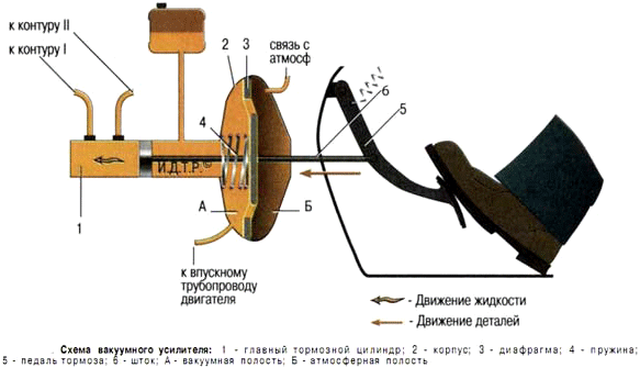
Diagram of the vacuum brake
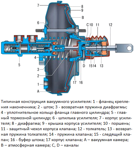
Booster Design of the signle-chamber vacuum booster
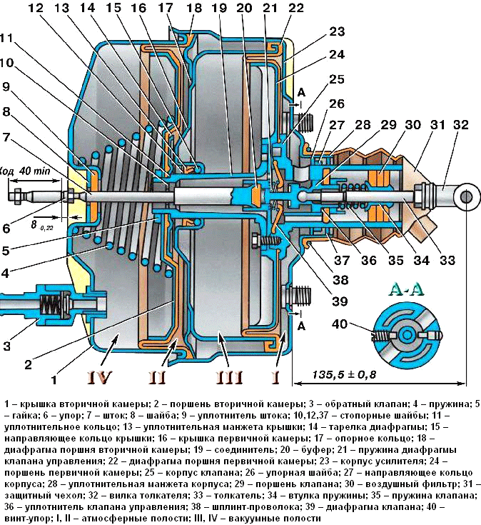
The design of the two-chambe vacuum booster
The vacuum amplifier works quite simply. When the pedal is depressed, the control valve (servo valve) is closed, but both cavities communicate through holes, a channel or a separate valve - they maintain reduced pressure, the diaphragm is in balance and does not move in either direction. At the moment of moving the pedal forward, the tracking valve is triggered, it closes the channel between the cavities and at the same time communicates the atmospheric cavity with the atmosphere, so the pressure in it increases sharply. As a result, a pressure difference occurs on the diaphragm, it moves towards the cavity with low pressure under the influence of high atmospheric pressure, and through the rod acts on the GTZ or GCS. Due to atmospheric pressure, the force on the pedal increases, which makes the pedal travel easier when braking or disengaging the clutch.
If the pedal stops in any intermediate position, then the tracking valve closes (since the pressure on both sides of its piston or special jet washer is equalized, and these parts sit on their seat due to the action of the spring) and the pressure in the atmospheric chamber ceases to change. As a result, the movement of the diaphragm and rod stops, the associated GTZ or GCS remains in the selected position. With a further change in the position of the pedal, the control valve opens again, the processes described above continue. Thus, the control valve provides the tracking action of the system, thereby achieving proportionality between the pedal press and the force generated by the entire mechanism.
When the pedal is released, the tracking valve closes, separating the atmospheric cavity from the atmosphere, while opening the holes between the cavities. As a result, the pressure drops in both cavities, and the diaphragm and the associated GTZ or GCS return to their original position due to the force of the spring. In this position, the VU is ready to work again.
As mentioned above, the most common source of vacuum for the VU is the intake manifold of the power unit, from this it is clear that when the engine is stopped, this unit will not work (although the vacuum remaining in the VU chamber, even after the engine stops, will be able to provide from one to three braking). Also, the VU will not work if the chambers are depressurized or the vacuum supply hose from the motor is damaged. But the braking system or clutch drive in this case will remain operational, although this will require more effort. The fact is that the pedal is directly connected to the GTZ or GCS through two rods running along the axis of the entire VU. So in case of various breakdowns, the VU rods will act as a conventional drive rod.
How to select, repair and maintain a vacuum amplifier
Practice shows that CWT and VUS have a significant resource and rarely become a source of problems. However, for various reasons, various malfunctions can occur in this unit, mainly loss of tightness of the chamber, damage to the diaphragm, malfunction of the valve and mechanical damage to parts. A malfunction of the amplifier is indicated by an increased resistance on the pedal and a decrease in its stroke. When such signs appear, it is necessary to diagnose the unit, in case of a malfunction, repair or replace the amplifier assembly.
Only those types and models of VUT and VUS that are recommended for installation by the vehicle manufacturer should be taken for replacement. In principle, it is permissible to use other parts, but they must have suitable characteristics and installation dimensions. It is unacceptable to use a unit that creates insufficient force - this will lead to a deterioration in the controllability of the vehicle and to an increase in driver fatigue. For example, in no case should you put a single-chamber VU instead of a two-chamber one. On the other hand, it makes no sense to install a more powerful amplifier, since when using it, the "pedal feeling" may be lost, and this replacement will require unjustified costs.
Also, when selecting an amplifier, it is necessary to take into account its configuration - these parts can be supplied assembled with a GTZ or GCS, or separately from them. Additionally, you may need to purchase fittings, slags, clamps and fasteners - all this should be taken care of in advance.
Replacement of the vacuum amplifier must be carried out in accordance with the repair instructions of the vehicle. Usually, it is enough to disconnect the stem from the pedal, remove the GTZ / GCS (if they are in good condition) and all hoses, then dismantle the amplifier, the installation of a new unit is performed in reverse order. If the VU changes in the assembly with the cylinder, then it is first necessary to drain the liquid from the system and disconnect the pipelines going to the circuits from the cylinder. When installing a new amplifier, it is necessary to adjust the pedal stroke, this may also be required during the further operation of the vehicle.
If the vacuum booster is correctly selected and replaced, the braking system or clutch actuator will immediately start working, ensuring effective control of the vehicle in all conditions.
Post time: Jul-13-2023