
In every modern vehicle there is a developed electrical network, the voltage in which is stabilized by a special unit - a relay-regulator. Read all about relay-regulators, their existing types, design and operation, as well as the selection and replacement of these parts in the article.
What is a voltage regulator relay?
Voltage regulator relay (voltage regulator) is a component of the vehicle's electrical system; A mechanical, electromechanical or electronic device that provides support for the voltage operating in the on-board power supply within certain limits.
The electrical system of vehicles is built in such a way that when the power unit is stopped, the battery (battery) acts as a power source, and when it is started, the generator converts part of the engine power into electricity. However, the generator has a significant drawback - the voltage of the current generated by it depends on the speed of the crankshaft, as well as on the current consumed by the load and the ambient temperature. To eliminate this drawback, an auxiliary device is used - a relay-regulator or simply a voltage regulator.
The voltage regulator solves several problems:
● Voltage stabilization - maintaining the voltage of the on-board network within the specified limits (within 12-14 or 24-28 volts with permissible deviations);
● Protection of the battery from discharge through the generator circuits when the engine is stopped;
● Certain types of regulators - automatic shutdown of the starter when the engine is successfully started;
● Certain types of regulators - automatic connection and disconnection of the generator from the battery to charge it;
● Certain types of regulators - changing the voltage of the on-board network depending on the current climatic conditions (transfer of the electrical system to summer and winter operation).
All vehicles, tractors and various machines are equipped with relay-regulators. The malfunction of this unit disrupts the operation of the entire electrical system, in some cases this can lead to breakdown of electrical equipment and fires. Therefore, a faulty regulator must be replaced as soon as possible, and for the correct choice of a new part, it is necessary to understand the existing types, design and principle of operation of regulators.
Types, design and principle of operation of the relay-regulator
Today, there are several types of relay-regulators, but their work is based on the same principles. Any regulator contains three interrelated elements:
- Measuring (sensitive) element;
- Comparison (control) element;
- Regulatory element.
The regulator is connected to the field winding of the generator (OVG), measuring and changing the current strength in it - this ensures voltage stabilization. In general, this system works as follows. The measuring element, built on the basis of a voltage divider, constantly monitors the current strength in the OVG and converts it into a signal coming to the comparison (control) element. Here, the signal is compared with the standard - the voltage value that normally should operate in the car's electrical system. The reference element can be built on the basis of vibration relays and zener diodes. If the signal coming from the measuring element corresponds to the reference (with a permissible deviation), then the regulator is inactive. If the incoming signal differs from the reference signal in one direction or another, then the comparison element generates a control signal coming to the regulating element built on relays, transistors or other elements. The regulating element changes the current in the OVG, which achieves the return of the voltage at the output of the generator to the required limits.
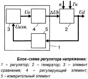
Voltage regulator block diagram
As already indicated, the regulator units are built on a different element base, on this basis the devices are divided into several types:
● Vibrating;
● Contact-transistor;
● Electronic transistor (contactless);
● Integral (transistor, made using integrated technology).
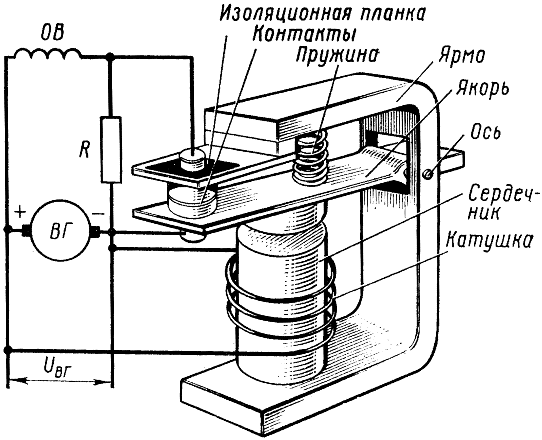
Diagram of the vibration relay-regulator
Historically, vibration devices were the first to appear, which, in fact, are called relay-regulators. In such a device, all three units can be combined in one design - an electromagnetic relay with normally closed contacts, although the measuring element can be made in the form of a divider on resistors. The tension force of the return spring acts as a reference value in the relay. In general, the relay-regulator works simply. With a low current on the OVG or a low voltage at the output of the generator (depending on the method of connecting the regulator), the relay does not work and current flows freely through its closed contacts - this leads to an increase in voltage. When the voltage rises, the relay is triggered, the voltage in the circuit drops and the relay is released, the voltage rises again and the relay is triggered again - this is how the relay switches to oscillation mode. When the voltage on the generator changes in one direction or another, the oscillation frequency of the relay changes, which ensures voltage stabilization.
At present, vibration relays, which have low efficiency and insufficient reliability, are no longer used on vehicles. At one time, they were supplanted by contact-transistor regulators, in which a vibration relay is used as a comparing/control element, and a transistor operating in key mode is used as a regulating element. Here, the transistor plays the role of relay contacts, therefore, in general, the operation of such a regulator is similar to that described above. Today, regulators of this type are practically replaced by contactless transistors of various designs.
In contactless transistor regulators, the relay is replaced by a simpler semiconductor device - a zener diode. The zener diode stabilization voltage is used as a reference value, and the control element is built on the basis of transistors. At low voltage, the zener diode and transistors are in such a state that the maximum current is supplied to the OVG, which leads to an increase in voltage. When the required voltage level is reached, the zener diode and transistors switch to another state and begin to operate in oscillatory mode, which, as in the case of a conventional relay, provides voltage stabilization.
Modern electronic regulators are built on transistors and can have a pulse-width modulator (PWM), through which the switching frequency of the circuit is set and the device can be introduced into the general automotive control system.
Non-contact transistor regulators can be performed on discrete elements and integrated technology. In the first case, conventional electronic components (zener diodes, transistors, resistors, etc.) are used, in the second case, the entire unit is assembled on a single chip or compact block of compact radio components filled with a compound.
The considered design has the simplest relay-regulators, in reality, more complex devices with various auxiliary units are used - starter control, preventing battery discharge through the field winding, correcting the operating mode depending on temperature, circuit protection, self-diagnosis and others. On many relay-regulators of tractors and trucks, the possibility of manual adjustment of the stabilization voltage is also implemented. This adjustment is performed using a variable resistor (in vibration devices - using a spring) by means of a lever or handle placed outside the housing.
Regulators are made in the form of small blocks mounted directly on the generator or in a convenient place on the vehicle. The device can be connected to the OVG and / or the output of the generator, or to the section of the on-board power supply where a stabilized voltage is required. In this case, one terminal of the OVG must be connected to the "+" or to the "-" on-board power supply.
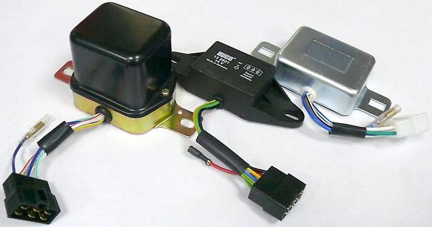
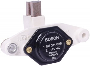
Voltage regulator relays for installation outside the generator
Issues of selection, diagnostics and replacement of voltage regulator relays
Various malfunctions can occur in relay-regulators, which in most cases are manifested by the absence of the battery charge current and, on the contrary, by the excessive charge current of the battery. The simplest check of the regulator can be carried out using a voltmeter - just start the engine and let it run at a frequency of 10-15 rpm and with the headlights on for 2500-3000 minutes. Then, without reducing the speed and without turning off the headlights, measure the voltage at the battery terminals - it should be 14.1-14.3 volts (for 24-volt twice as high). If the voltage is much lower or higher, then this is an occasion to check the generator, and if it is in order, replace the regulator.
A relay-regulator of the same type and model that was installed earlier should be taken for replacement. It is especially necessary to pay attention to the order of connection of the regulator to the on-board network (to which terminals of the generator and other elements), as well as to the supply voltage and currents. Replacement of the part must be carried out according to the instructions, work can be performed only when the engine is stopped and the terminal is removed from the battery. If all the recommendations are followed, and the regulator is selected correctly, then it will immediately start working, ensuring the normal functioning of the electrical system.
Post time: Jul-13-2023