
In the operation of the crank mechanism of piston engines, one of the key roles is played by the parts connecting the pistons and the crankshaft - connecting rods. Read about what a connecting rod is, what types these parts are and how they are arranged, as well as the correct selection, repair and replacement of connecting rods in this article.
What is a connecting rod and what place does it occupy in the engine?
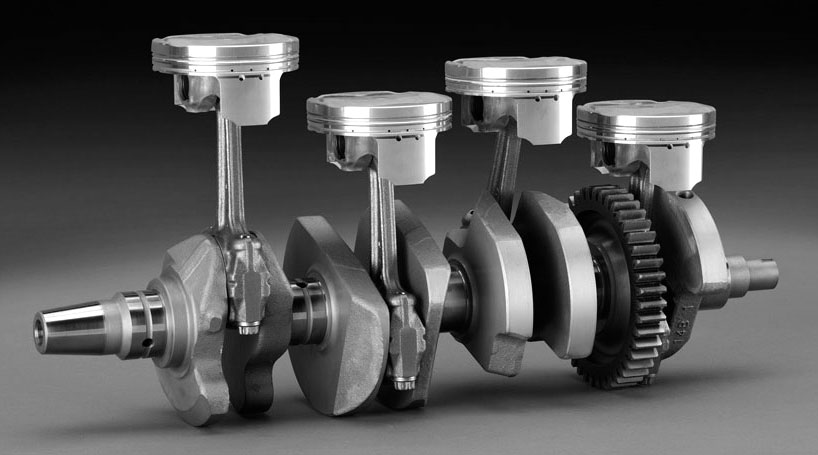
The connecting rod is a component of the crank mechanism of piston internal combustion engines of all types; A detachable part designed to connect the piston to the corresponding crankshaft journal.
This part performs several functions in the engine:
● Mechanical connection of the piston and crankshaft;
● Transmission from the piston to the crankshaft of the moments arising during the working stroke;
● Conversion of reciprocating movements of the piston into rotational motion of the crankshaft;
● Lubricant is supplied to the piston pin, piston walls (for additional cooling) and cylinder, as well as to timing parts in power units with a lower camshaft.
In motors, the number of connecting rods is equal to the number of pistons, each connecting rod is connected to the piston (through a bronze sleeve and pin), and the lower part is connected to the corresponding crankshaft journal (through plain bearings). As a result, a hinged structure is formed, which ensures free movement of the piston in a vertical plane.
Connecting rods play an important role in the operation of the power unit, and their breakdown often completely disables the engine. But for the right choice and replacement of this part, it is necessary to understand its design and features.
Types and design of connecting rods
Today, there are two main types of connecting rods:
● Standard - conventional connecting rods used in all types of piston engines;
● Paired (articulated) - a unit consisting of a conventional connecting rod and a connecting rod hinged to it without a crank head, such units are used in V-shaped motors.
The design of the connecting rods of the internal combustion engine is established and practically brought to perfection (as far as possible with the modern development of technology), therefore, despite the huge variety of engines, all these parts are arranged in the same way.
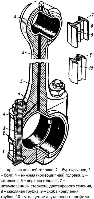
The connecting rod is a collapsible (composite) part, in which three parts are distinguished:
● Rod;
● Piston (upper) head;
● Crank (bottom) head with removable (detachable) cover.
The rod, the upper head and half of the lower head are one part, all these parts are formed at once in the manufacture of the connecting rod. The cover of the lower head is a separate part that is connected to the connecting rod in one way or another. Each of the parts of the connecting rod has its own design features and functionality.
Connecting rod design
Rod. This is the basis of the connecting rod that connects the heads and ensures the transfer of force from the piston head to the crank. The length of the rod determines the height of the pistons and their stroke, as well as the overall height of the engine. To achieve the required rigidity, various profiles are attached to the rods:
● I-beam with the arrangement of shelves perpendicular or parallel to the axes of the heads;
● Cruciform.
Most often, the rod is given an I-beam profile with a longitudinal arrangement of shelves (on the right and left, if you look at the connecting rod along the axes of the heads), the rest of the profiles are used less frequently.
A channel is drilled inside the rod to supply oil from the lower head to the upper head, in some connecting rods side bends are made from the central channel to spray oil on the cylinder walls and other parts. On I-beam rods, instead of a drilled channel, a metal oil supply tube connected to the rod with metal brackets can be used.
Usually, the rod is marked and marked for the correct installation of the part.
Piston head. A hole is carved in the head, into which a bronze sleeve is pressed, which plays the role of a plain bearing. A piston pin is installed in the sleeve with a small gap. To lubricate the friction surfaces of the pin and the sleeve, a hole is made in the latter to ensure the flow of oil from the channel inside the connecting rod rod.
Crank head. This head is detachable, its lower part is made in the form of a removable cover mounted on the connecting rod. The connector can be:
● Straight - the plane of the connector is at right angles to the rod;
● Oblique - the plane of the connector is made at a certain angle.
| Connecting rod with straight cover connector | Connecting rod with oblique cover connector |
The most common parts with a straight connector, connecting rods with an oblique connector are more often used on V-shaped power units and diesel engines, they are more convenient for installation and reduce the size of the power unit. The cover can be attached to the connecting rod with bolts and studs, less often a pin and other connections are used. There can be two or four bolts (two on each side), their nuts are fixed with special locking washers or cotter pins. To ensure maximum connection reliability, bolts can have a complex profile and be supplemented with auxiliary parts (centering bushings), so the fasteners of connecting rods of various types are not interchangeable.
The cover can be made at the same time with the connecting rod or separately. In the first case, after the connecting rod is formed, the lower head is split into two parts to make the cover. To ensure a reliable connection and ensure the stability of the connection in the event of transverse moments, the docking surfaces of the connecting rod and the cover are profiled (toothed, with a rectangular lock, etc.). Regardless of the manufacturing technology of the connecting rod, the hole in the lower head is bored in the assembly with the cover, so these parts should only be used in pairs, they are not interchangeable. To prevent steaming of the connecting rod and cover, markers in the form of marks of various shapes or numbers are made on them.
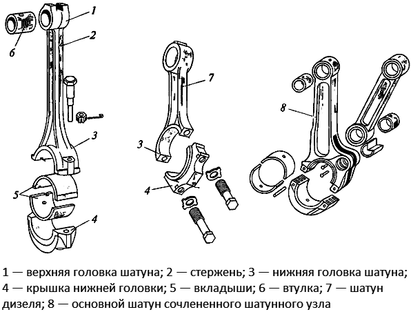
Design of connecting rods of various types
Inside the crank head, a main bearing (liner) is installed, made in the form of two half-rings. To fix the earbuds, there are two or four grooves (grooves) inside the head, which include the corresponding whiskers on the liners. On the outer surface of the head, an oil passage outlet can be provided to spray oil on the cylinder walls and other parts.
In articulated connecting rods, a protrusion with a bored hole is made above the head, into which the pin of the lower head of the trailed connecting rod is inserted. The trailed connecting rod itself has a device similar to a conventional connecting rod, but its lower head has a small diameter and is non-separable.
Connecting rods are made by stamping or forging, however, the cover of the lower head can be cast. For the manufacture of these parts, various grades of carbon and alloy steels are used, which can work normally under high mechanical and thermal loads.
Issues of maintenance, repair and replacement of connecting rods
Connecting rods during engine operation are subject to slight wear (since the main loads are perceived by the liners in the lower head and the sleeve in the upper head), and deformations and breakdowns in them occur either with serious engine malfunctions or as a result of its long-term intensive use. However, when performing some repair work, it is necessary to dismantle and disassemble the connecting rods, and the overhaul of the power unit is often accompanied by the replacement of connecting rods and related parts.
Disassembly, dismantling and subsequent installation of connecting rods requires compliance with certain rules:
● The covers of the lower heads should be installed only on the "native" connecting rods, the breakage of the cover requires a complete replacement of the connecting rod;
● When installing connecting rods, it is necessary to observe their installation order - each connecting rod must take its place and have the correct spatial orientation;
● Tightening of nuts or bolts must be carried out with a certain force (using a torque wrench).
Particular attention should be paid to the orientation of the connecting rod in space. There is usually a mark on the rod, which, when mounted on an in-line motor, must face its front and coincide with the direction of the arrow on the piston. In V-shaped motors, in one row, the mark and the arrow should look in one direction (usually the left row), and in the second row - in different directions. This arrangement ensures the balancing of the KShM and the motor as a whole.
In case of breakage of the cover, in case of torsion, deflections and other deformations, as well as in case of destruction, the connecting rods are completely replaced. The new connecting rod must be of the same type and catalog number as the one installed on the motor earlier, but this part still needs to be selected by weight to maintain engine balancing. Ideally, all connecting rod and piston groups of the engine should have the same weight, but in reality all connecting rods, pistons, pins and liners have different masses (especially if parts of repair dimensions are used), so the parts have to be weighed and completed by weight. The weight of the connecting rods is determined by taking into account the weight of each of its heads.
Disassembly, replacement and assembly of connecting rods and connecting rod-piston groups must be carried out in strict accordance with the instructions for repair and maintenance of the vehicle. In the future, the connecting rods do not need special maintenance. With proper selection and installation of connecting rods, the engine will provide the necessary performance in all operating conditions.
Post time: Aug-05-2023