
For comfortable and tireless transmission control on modern cars, a hydraulic clutch drive is used, one of the main roles in which is played by the master cylinder. Read about the clutch master cylinder, its types, design and operation, the correct choice and replacement in this article.
What is a clutch master cylinder?
Clutch master cylinder (GVC) - a hydraulic drive unit for turning on and off the clutch of manually controlled transmissions (manual transmissions); A hydraulic cylinder that converts the force from the driver's leg into the pressure of the working fluid in the drive circuit.
The GVC is one of the main components of the hydraulic clutch actuator. The master and slave cylinders, connected by a metal pipeline, form a sealed circuit of the hydraulic drive, with the help of which the clutch is turned off and engaged. The GVC is installed directly behind the clutch pedal and connected to it by a rod (pusher), the slave cylinder is mounted on the clutch housing (bell) and connected by a rod (pusher) to the clutch release fork.
The master cylinder plays an important role in the operation of the transmission, when it breaks down, driving the vehicle becomes difficult or completely impossible. But in order to make a purchase of a new cylinder, it is necessary to understand the design and features of this mechanism.
Types of clutch master cylinders
All GCPs have fundamentally the same design and principle of operation, but are divided into several varieties according to the location and design of the tank with the working fluid, the number of pistons and the overall design of the body.
According to the location and design of the tank, the cylinders are:
● With an integrated reservoir for working fluid and a remote tank;
● With a remote tank;
● With a tank located on the cylinder body.
| Clutch master cylinder with integrated reservoir | Clutch master cylinder with remote reservoir | Clutch master cylinder with reservoir mounted on the body |
The first type of GCS is an outdated design that is rarely used today. Such a mechanism is installed vertically or at a certain angle, in its upper part there is a tank with working fluid, the supply of which is replenished from the remote tank. The cylinders of the second and third types are already more modern devices, in one of them the tank is remote and connected to the cylinder by means of a hose, and in the other the tank is mounted directly on the cylinder body.
According to the number of pistons of GCS, there are:
● With one piston;
● With two pistons.
| Single-piston clutch master cylinder | Clutch master cylinder with two pistons |
In the first case, the pusher is connected to a single piston, so the force from the clutch pedal is transmitted directly to the working fluid. In the second case, the pusher is connected to an intermediate piston, which acts on the main piston and then on the working fluid.
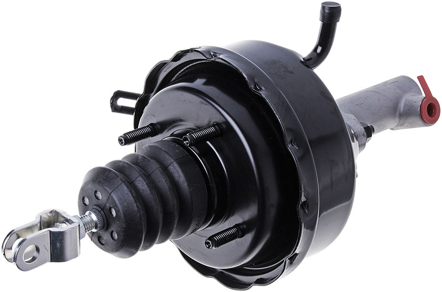
Finally, GCAs can have various design features, for example - on some cars, this device is made in a single case with the master brake cylinder, the cylinders can also be located vertically, horizontally or at a certain angle, etc.
The design and principle of operation of the clutch master cylinders
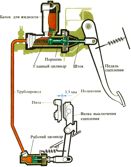
Typical diagram of a hydraulic clutch release drive
The most simple is the arrangement of GCS with a tank removed and installed on the body. The basis of the device is a cylindrical cast case, on which eyelets for mounting bolts and other parts are made. At one end, the body is closed with a threaded plug or a plug with a fitting for connection to the pipeline. If the body is closed with a blind plug, then the fitting is located on the side surface of the cylinder.
In the middle part of the cylinder, there is a fitting for connecting to the tank by means of a hose or a seat for installing the tank directly on the body. Under the fitting or in the seat in the cylinder housing, two holes are made: a compensation (inlet) hole of small diameter and an overflow hole of increased diameter. The holes are arranged in such a way that when the clutch pedal is released, the compensation hole is located in front of the piston (from the side of the drive circuit), and the bypass hole is located behind the piston.
A piston is installed in the body cavity, on one side of which there is a pusher connected to the clutch pedal. The end of the body on the pusher side is covered with a corrugated protective rubber cap. When the clutch pedal is depressed, the piston is retracted to the extreme position by a return spring located inside the cylinder. Two-piston GCAs use two pistons located one after the other, between the pistons there is an O-ring (cuff). The use of two pistons improves the tightness of the clutch drive circuit and increases the reliability of the entire system.
Rod. This is the basis of the connecting rod that connects the heads and ensures the transfer of force from the piston head to the crank. The length of the rod determines the height of the pistons and their stroke, as well as the overall height of the engine. To achieve the required rigidity, various profiles are attached to the rods:
● I-beam with the arrangement of shelves perpendicular or parallel to the axes of the heads;
● Cruciform.
Most often, the rod is given an I-beam profile with a longitudinal arrangement of shelves (on the right and left, if you look at the connecting rod along the axes of the heads), the rest of the profiles are used less frequently.
A channel is drilled inside the rod to supply oil from the lower head to the upper head, in some connecting rods side bends are made from the central channel to spray oil on the cylinder walls and other parts. On I-beam rods, instead of a drilled channel, a metal oil supply tube connected to the rod with metal brackets can be used.
Usually, the rod is marked and marked for the correct installation of the part.
Piston head. A hole is carved in the head, into which a bronze sleeve is pressed, which plays the role of a plain bearing. A piston pin is installed in the sleeve with a small gap. To lubricate the friction surfaces of the pin and the sleeve, a hole is made in the latter to ensure the flow of oil from the channel inside the connecting rod rod.
Crank head. This head is detachable, its lower part is made in the form of a removable cover mounted on the connecting rod. The connector can be:
● Straight - the plane of the connector is at right angles to the rod;
● Oblique - the plane of the connector is made at a certain angle.
| Connecting rod with straight cover connector | Connecting rod with oblique cover connector |
Such cylinders work as follows. When the clutch pedal is released, the piston is in the extreme position under the influence of the return spring and atmospheric pressure is maintained in the clutch drive circuit (since the working cavity of the cylinder is connected to the reservoir through the compensation hole). When the clutch pedal is pressed, the piston moves under the influence of foot force and tends to compress the fluid in the drive circuit. When the piston moves, the compensation hole closes and the pressure in the drive circuit increases. At the same time, fluid flows through the bypass port behind the reverse side of the piston. Due to the increase in pressure in the circuit, the piston of the working cylinder moves and moves the clutch release fork, which pushes the release bearing - the clutch is disengaged, you can change gear.
At the moment of release of the pedal, the piston in the GVC returns to its original position, the pressure in the circuit drops and the clutch is engaged. When the piston is returned, the working fluid accumulated behind it is squeezed out through the bypass port, which leads to a slowdown in the movement of the piston - this ensures a smooth engagement of the clutch and the return of the entire system to its original state.
If there is a leakage of working fluid in the circuit (which is inevitable due to insufficient tightness of joints, damage to seals, etc.), then the required amount of liquid comes from the tank through the compensation hole. Also, this hole ensures the constancy of the volume of the working fluid in the system when its temperature changes.
The design and operation of the cylinder with an integrated reservoir for the working fluid is somewhat different from that described above. The basis of this GVC is a cast body mounted vertically or at an angle. In the upper part of the body there is a reservoir for the working fluid, under the tank there is a cylinder with a spring-loaded piston, and a pusher connected to the clutch pedal passes through the tank. On the wall of the tank there may be a plug for topping up the working fluid or a fitting for connecting to the remote tank.
The piston in the upper part has a recess, a hole of small diameter is drilled along the piston. The pusher is installed above the hole, in the retracted state there is a gap between them through which the working fluid enters the cylinder.
Such a GVC works easily. When the clutch pedal is released, atmospheric pressure is observed in the hydraulic circuit, the clutch is engaged. At the moment of pressing the pedal, the pusher moves down, closes the hole in the piston, sealing the system, and pushes the piston down - the pressure in the circuit rises, and the working cylinder activates the clutch release fork. When the pedal is released, the described processes are performed in reverse order. Leaks of the working fluid and changes in its volume due to heating are compensated through a hole in the piston.
The right choice, repair and replacement of GVCs
During the operation of the vehicle, the GCC is subjected to high loads, which leads to gradual wear of its individual parts, primarily the piston cuffs (pistons) and rubber seals. Wear of these components is manifested by leaks of working fluid and deterioration of the clutch (pedal dips, the need to squeeze the pedal several times, etc.). The problem is solved by replacing worn parts - for this you need to purchase a repair kit and perform simple work. Dismantling, disassembly, replacement of parts and installation of the cylinder should be carried out in accordance with the instructions for repair and maintenance of the vehicle.
In some cases, there are fatal malfunctions of the clutch master cylinder - cracks, fractures of the housing, breakage of fittings, etc. For replacement, you need to choose a cylinder of the same type and catalog number that was installed on the car earlier, otherwise the cylinder will either not be able to be installed at all, or the clutch will not work correctly.
After installing a new GVC, it is necessary to adjust the clutch in accordance with the recommendations of the instructions. Usually, the adjustment is performed by changing the length of the rod (using the appropriate nut) of the pedal and the position of the piston pusher, the adjustment must be set by the free stroke of the clutch pedal recommended by the car manufacturer (25-45 mm for various cars). In the future, it is necessary to replenish the liquid level in the tank and monitor the appearance of leaks in the system. With proper adjustment and regular maintenance, the GVCs and the entire clutch drive will provide confident transmission control in all conditions.
Post time: Aug-05-2023